reference: https://github.com/VasanthVanan/computer-networking-top-down-approach-notes (this note is based on the linked note)
Chapter 0: something to know
0.1 Network of Networks

- end systems = host = connected devices, ISPs = Internet Service Providers
- Access Networks: the network that physically connects an end system to the first router.
- Peering: direct traffic exchange between ISPs
- IXPs: Internet Exchange Points facilitate ISPs’ direct connections.
0.2 Throughput
Instantaneous vs. Average
the throughput is determined by the slowest link in a connection - the bottleneck.
some apps require minimum amount of throughput to be effective (e.g. multimedia), while
elastic appsmake use of whatever throughput they get (finish in appointted time is ok, won’t require instantaneous speed)
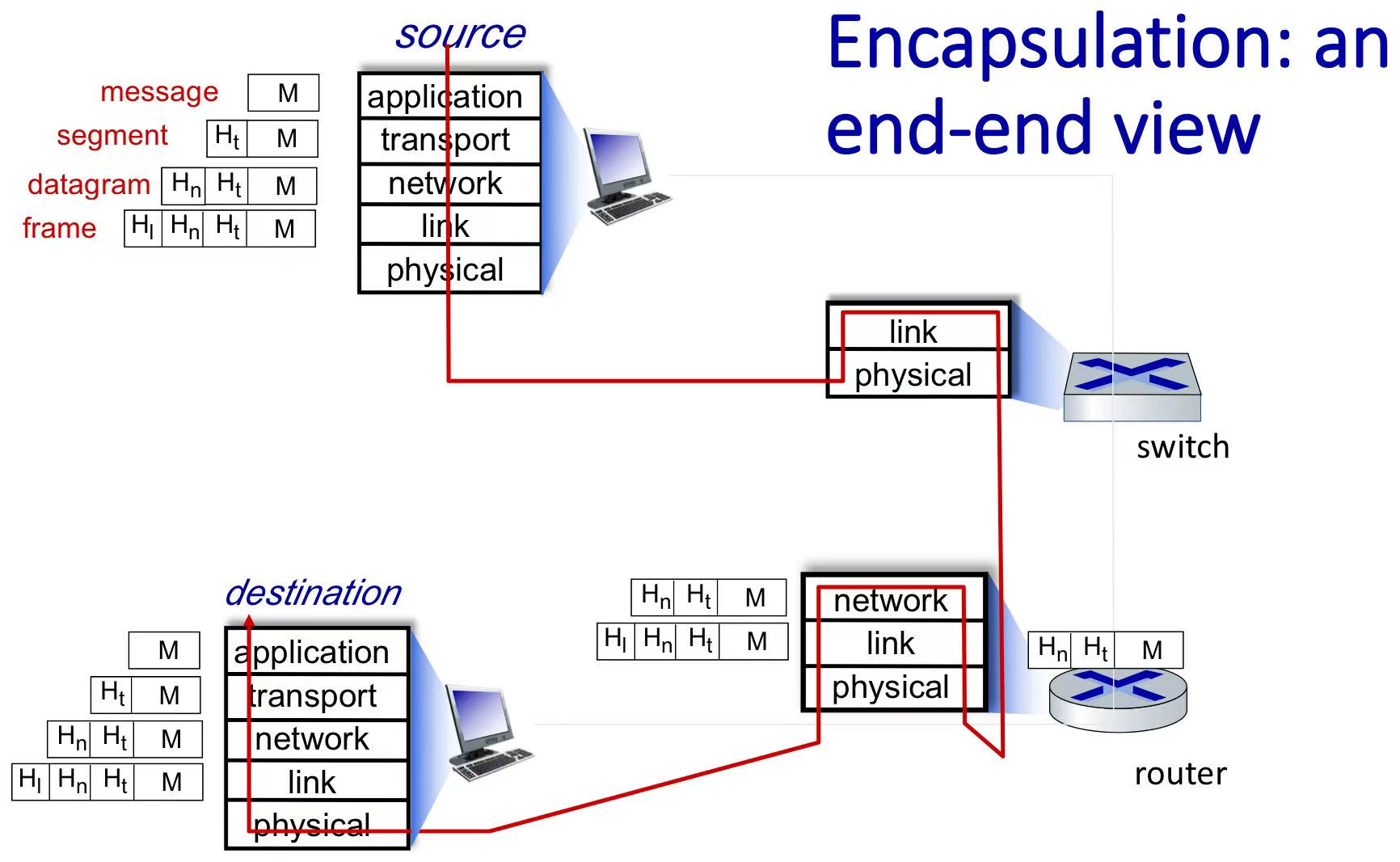
0.3 Five Protocol Layers
application layer supporting network applications, such as HTTP, IMAP, SMTP, DNS
transport layer process-process data transfer, such as TCP, UDP
Layer-3: network layer routing of datagrams from source host to destination host, such as IP, routing protocols
Layer-2: data link layer data transfer between physical neighboring nodes
physical layers
Encapsulation: Data is encapsulated as it moves down the protocol stack. Each layer adds its header information to the data received from the layer above, creating a packet with header fields and a payload field.
Internet protocols define the format, order of messages sent and received among network entities, and actions taken on message transmission, receipt.
0.4 Network Security
attacks
- packet sniffing
- IP spoofing: injection of packet with false source address
- denial of service(DoS): flood the network with packets
defense authentication, confidentiality, integrity checks, access restrictions, firewalls
Chapter 1: Application Layer
1.1 something to know
Application Layer Protocols Define:
- Message Types. e.g., Requests, Responses
- Message Syntax: The structure of the message, including fields and their delimiters.
- Message Semantics: The meaning of the information contained within the fields.
- Rules for Timing and Order of Sending and Responding to Messages
content distribution networks (CDNs): store/serve copies of popular content at multiple geographically distributed sites
1.2 Two Architecture
- Client-Server Architecture:
- server always-on host, clients intermittently connected
- Peer-to-Peer (P2P) Architecture:
- Scalability: new peers bring new service capacity as well as new service demands
- time to distribute file from one server to N peers
- using client-server approach: $D_{C-S} \geq max {NF/u_s, F/d_{min}}$ $u_s$ is server upload speed, $d_{min}$ is min client download rate
- using P2P approach: $D_{P2P} \geq max {F/d_{min}, NF/\sum u_i}$
- BitTorrent
- torrent = group of peers exchanging chunks of a file
- tracker = server that maintains a list of peers in the torrent
- sending chunks: tit-for-tat
- Alice sends chunks to those four peers currently sending her chunks at highest rate
- every 30 secs: randomly select another peer, starts sending chunks
- if the new peer does well, it becomes one of Alice’s top four peers
- last coupon dilemma: if a client has almost all the chunks, it’s difficlut for it to get the final one.
- solution: Send all uncoded chunks and the same number of encoded chunks. Client only needs any half of the total to fully reconstruct the file.
1.3 Application Layer Protocol: Web and HTTP
- HTTP(HyperText Transfer Protocol): the primary application layer protocol of the World Wide Web. TCP underlying.
- Stateless: don’t store client specific information. with cookies it can but not required
1.3.1 Non Persistent and Persistent Connections
round trip time (RTT): the time for a small packet to travel from client to server and back.

- three way handshake before receiving file(s).
- In the third handshake, the client sends an HTTP request message along with an acknowledgment into the TCP connection.
- The server responds by sending the HTML file over the established connection.
- then, Non-persistent HTTP server closed the connection while Persistent HTTP server keep the connection open for multiple requests.
- Non-persistent HTTP response time = 2RTT + file transmission time
Persistent HTTP response time = 1RTT + file transmission time (avg)
1.3.2 HTTP version
- HTTP1.0: Non-persistent
- HTTP1.1: persistent, introduced multiple, pipelined GETs over singe TCP connection
first-come-first-serve -> head-of-line blocking = small object may have to wait for transmission behind large objects. - HTTP/2: solve HOL - breaks messages into frames and interleaves them
- HTTP/3: add security and congestion-control over UDP
QUIC: Quick UDP Internet Connections
1.3.3 HTTP Message Format:
HTTP messages have two types: request messages and response messages. Click here for more info
Request:
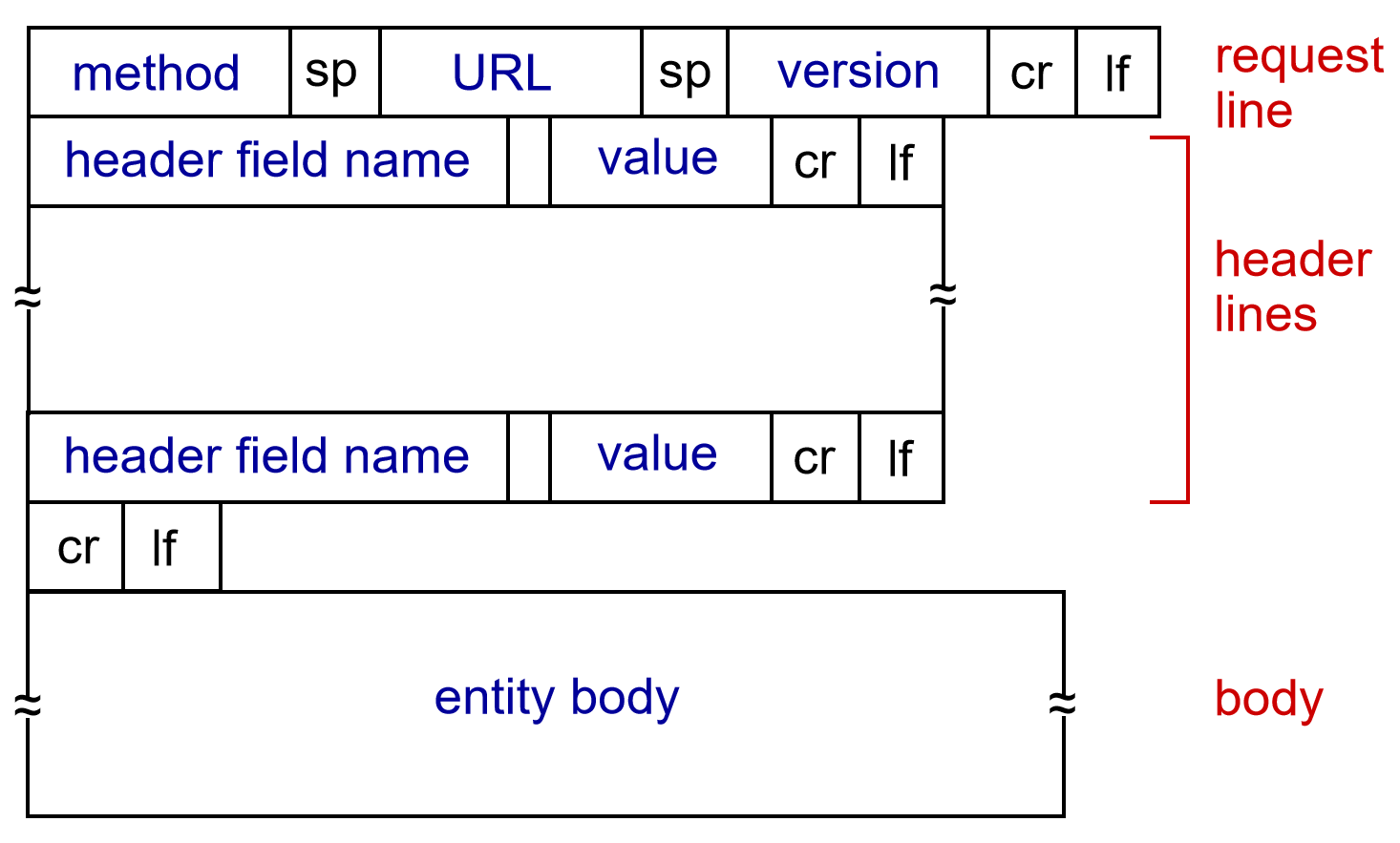
- methods: POST, GET, HEAD, PUT …
Response:
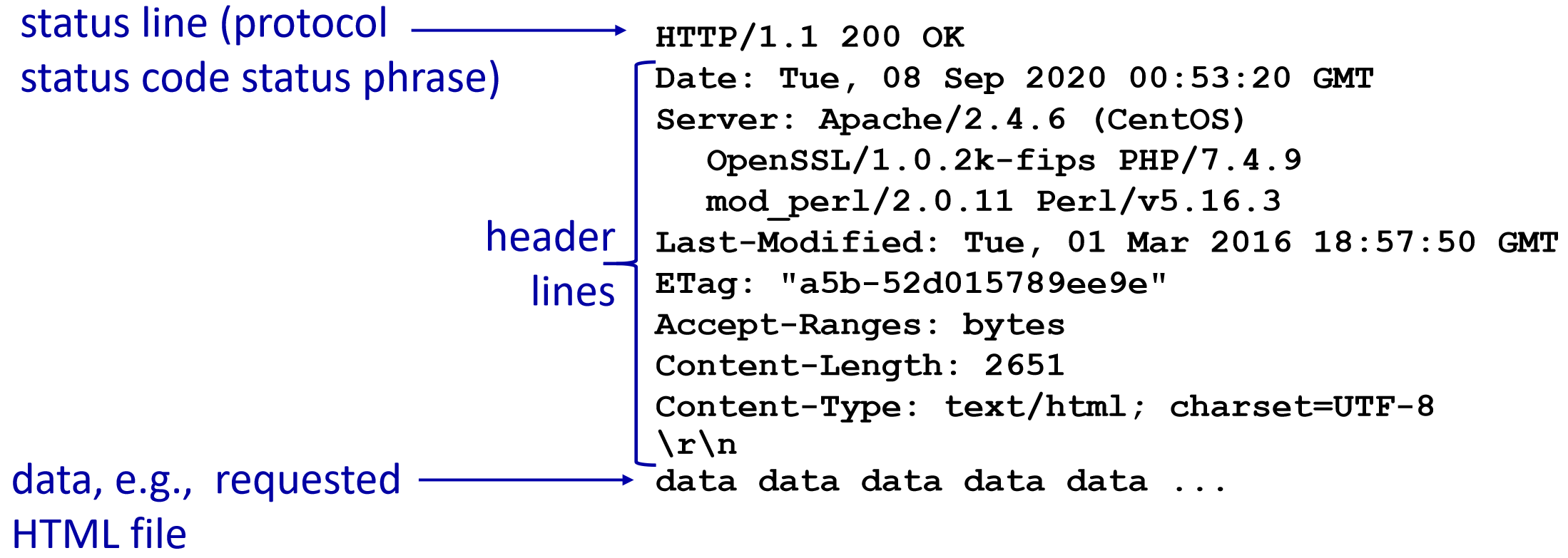
- status code: e.g. 200-ok 301-moved permanently 400-bad request 404-not found 505-http version not supported. for more, Click here for more info
Header Lines: provide additional information in HTTP messages. request headers may include User-agent, Accept-language… response: Date, Server, Last-Modified, Content-Length, and Content-Type…
1.3.4 Web Caches/Proxy servers
- Caches store copies of requested objects, reducing the need to fetch them from the origin server (which means lower bandwidth costs) and faster.
- Caches serve as both servers (to clients) and clients (to servers) in the caching process.
an cache example
- Scenario: Access link rate = 1.54 Mbps, RTT to server = 2s, web object = 100KB, request rate = 15/sec, avg data rate = 1.50 Mbps. Performance: Access link utilization = (request rate × object size) / access link rate = (15 × 100 × 10³) / (1.54 × 10⁶) ≈ 0.97 (high queuing delay) LAN utilization = (15 × 100 × 10³) / (1 × 10⁹) = 0.0015 End-to-end delay = Internet delay + access link delay + LAN delay = 2s + “minutes” + usecs.
- Option 1 (expensive): Increase access link to 154 Mbps. Access link utilization = (15 × 100 × 10³) / (154 × 10⁶) ≈ 0.0097 (low queuing delay) LAN utilization = 0.0015 End-to-end delay = 2s + “msecs”
- Option 2 (cheap): Cache installed, same 1.54 Mbps link. Hit Tate = 0.4 Data rate over access link = 0.6 × 1.50 Mbps = 0.9 Mbps. Access link utilization = 0.9 / 1.54 ≈ 0.58 (low queuing delay). Delay for 60% requests from origin = 2s + 0.01s (transmission) = 2.01s. Delay for 40% requests from cache = “msecs”. Weighted average delay = (0.6 × 2.01s) + (0.4 × “msecs”) ≈ 1.2s.
- Conditional GET checks for freshness by comparing the
If-Modified-Sinceheader with object modification date. If an object hasn’t changed, a304 Not Modified responseallows the cache to serve the locally cached object.
1.4 Application Layer Protocol: SMTP
1.4.1 Email Basis
email components:
- User Agents: a.k.a mail reader. composing, editing, reading mail msg.
e.g. Microsoft Outlook, Apple Mail, etc. - Mail Servers
- SMTP (Simple Mail Transfer Protocol)
- User Agents: a.k.a mail reader. composing, editing, reading mail msg.
Mail Message Structure
- Email messages consist of a
headerand abody, which are separated by a blank line (that is, by CRLF). - header: from, to, subject
- body: the msg, ASCII characters only
- Email messages consist of a
1.4.2 SMTP process
using TCP, persistent connection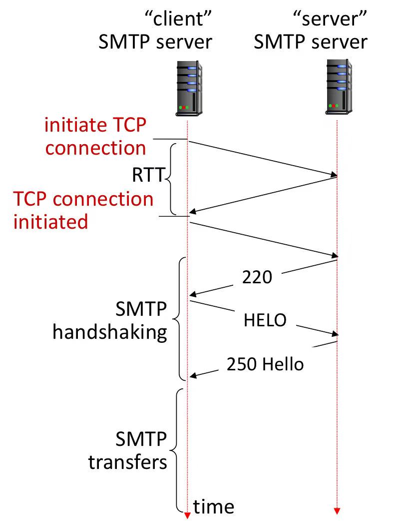
220 = server ready, HELO = identify + ask supported func, 250 Hello = list supported func
1.4.3 Mail Access Protocols

- SMTP: delivery/storage of e-mail msg to receiver’s server
- IMAP: provides retrieval, deletion, folders of stored msg on e-mail server
- HTTP: provides web-based interface on top of STMP (to send), IMAP (or POP) to retrieve e-mail messages
1.5 Application Layer Protocol: DNS (Domain Name System)
1.5.1 Distributed, Hierarchical Database
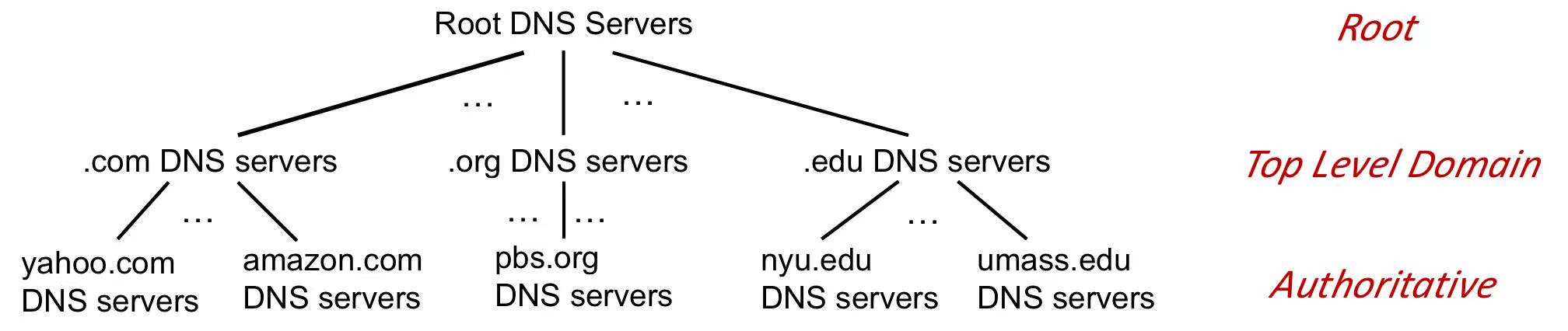
- Top-Level Domain (TLD) Servers:
- Every domain name ends with a TLD (google.com, bbc.co.uk), and TLD servers help route queries to the appropriate authoritative DNS server.
- manage top-level domains such as
.com,.org,.net,.edu,.aero,.jobs,.museums, and country domains like.cn,.uk,.fr,.ca,.jp.
- Authoritative DNS Servers:
- Managed by an organization or service provider.
- Provide authoritative hostname-to-IP mappings for the organization’s domain names.
- Local DNS Name Servers
- When a host makes a DNS query, it is sent to its local DNS server, which acts a proxy, forwarding the query into the DNS server hierarchy.
- it will first check its local cache for a recent name-to-address translation, if fail then forwrd
1.5.2 Recursive vs Iterative DNS Queries

1.5.3 DNS Records
- DNS servers store resource records (RRs).
- A RR is a four tuple: (Name, Value, Type, TTL).
- TTL (Time to Live) determines when a resource should be removed from a cache.
- Types of resource records (= DNS function):
Type=A/AAAA: name = hostname, value = IP address.Type=NS: name = domain, value = hostname of authoritative name server for this domain.Type=CNAME: name = alias name for some “canonical” (the real) name, value = canonical name.Type=MX: value = name of SMTP mail server associated with name.
+ DNS balances traffic among replicated servers by rotating IP addresses within replies, ensuring even distribution
1.6 video streaming
streaming video = encoding + DASH + playout buffering
1.6.1 encoding
- coding: use redundancy within and between image to decrease # bits used to encode image
e.g. spatial(within image) and temporal (between images)- CBR (constant bit rate) and VBR (variable bit rate, changing as amount of spatial, temporal coding changes)
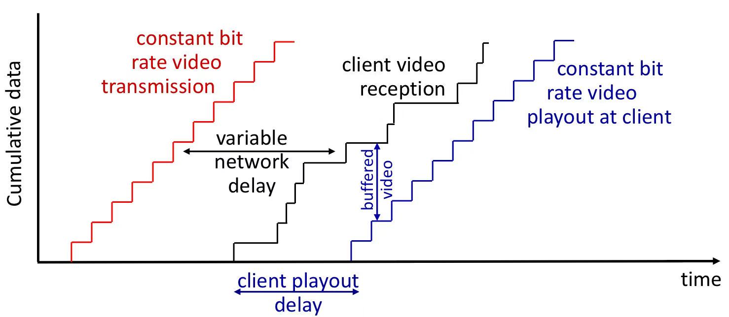
1.6.2 streaming stored video
- client playing out early part of video while sever still sending later part of it. playout timing must match original timing.
- main challenges:
- server-to-client bandwidth will vary over time.
- network delays are variable (jitter)
- solution: client-side buffer
1.6.3 DASH: Dynamic Adaptive Streaming over HTTP
Server:
- Splits video into chunks, encoded at multiple bitrates.
- Stores different bitrates in separate files, replicated in CDN nodes.
- Provides a manifest file with URLs for chunk retrieval.
Client:
- Estimates bandwidth and fetches chunks dynamically.
- Selects the highest sustainable bitrate.
- Adjusts bitrate and source server based on network conditions.
Chapter 2: Transport Layer
2.1 Multiplexing and Demultiplexing
something to know
Process Addressing: IP Adderss (the host) + Port Number (the process).
Processes Communicating: by exchanging messages
- client process: initiates communication
- server process: waits to be connected (to be noticed: P2P also has server process)
Socket: the interface between the application layer and the transport layer within a host, which messages must pass through.

Demultiplexing as receiver
use header info to deliver received segments to correct socket
Multiplexing as sender
- handle data from multiple sockets, add transport header (later used for demultiplexing)
- Each datagram carries one transport-layer segment. Each segment has source, destination port number (16 bits each)
Connectionless/Connection Oriented
- connectionless: UDP demultiplexing with only port number( no IP )
- connection oriented: TCP socket identified by 4-tuple: 2 IP + 2 port, which all used for demultiplexing
- demux: recerver uses all four values to direct segment
they both need IP address for routing, but TCP is based on connection so it need IP even when finding the right process to check connection
- TCP & UDP Both Not Provided: throughput or timing (delay & bandwidth) guarantees (because of packet switching) or security.
2.2 Principals of Reliable Data Transfer
ARQ = Automatic Repeat reQuest
2.2.1 RDT 3.0:
receiver sends an acknowledgment (ACK) in response to a pocket. If the sender doesn’t receive an ACK within a certain time, it retransmits.
improve: Pipelining
- transmit multiple packets before waiting for acknowledgments (by expanding the range of sequence numbers)
- the account of packets is restricted by congestion control.
- Two basic approaches for pipelined error recovery are
Go Back Nandselective repeat.
2.2.2 Go-Back-N (GBN)
sliding window protocol
Animation: Go-Back-N ARQ
Sender Behavior:
- able/timeout -> send
- cumulative acknowledgment:
- one ack arriving = former pkt done
- thus move window forward to begin at n + 1
Receiver Behaviour
- ACK-only: always send ACK for correctly-received packet so far, with highest in-order seq
e.g. b lost but c arrive -> ack a
- ACK-only: always send ACK for correctly-received packet so far, with highest in-order seq

- Performance Issues:
- suffer when the window size is large.
- A single packet error can trigger unnecessary retransmissions, potentially filling the pipeline with these redundant packets.
2.2.3 Selective Repeat (SR)
Animation: Selective Repeat ARQ
Sender Actions:
- if next available seq# in window, send packet
- Use individual timers for each unACKed pkt. when one timeout, retransmits it
- ACK Received:
- mark packet n as received
- if n smallest unACKed seq# -> advance window base to next unACKed seq#
Receiver Actions:
individually ACKs all correctly received packets.
buffers packets, as needed, for in-order delivery to upper layer.
packet n in [rcvbase, rcvbase+N-1]
- send ACK(n)
- out-of-order: buffer
- in-order: deliver (also deliver buffered, in-order packets), advance window to next not-yet-received packet
packet n in [rcvbase-N,rcvbase-1]: ACK(n)
otherwise: ignore
perform better when a single pkt is lost, but worse when multiple pkts are lost.
the sequence number range must be ≥ 2 × the Window Size: to prevent the receiver from being unable to distinguish between new data packets and retransmitted data packets.
The ACK of TCP is based on byte sequence numbers for confirmation, while the ACK of ARQ (Stop-and-Wait, GBN, SR) is based on packets/frames for confirmation.
2.3 Congestion Control
Causes/costs of congestion
- delay increases as capacity approached
- loss/retransmission decreases effective throughput
Explicit congestion notification (ECN):
- two bits in IP header marked by router to indicate congestion
- congestion indication carried to destination, destination sets ECE bit on ACK segment to notify sender of congestion
- involves both IP (IP header ECN bit marking) and TCP (TCP header C,E bit marking)
2.3.1 Loss Based Control
- AIMD: additive increase, multiplicative decrease (probeing line like sawtooth)
- influence the cwnd directly to control sending rate
- increase sending rate by 1 maximum segment size every RTT until loss detected
- cut sending rate in half at each loss event
2.3.2 Delay based Congestion Control
$RTT_{min}$ = minimum observed RTT (uncongested path)
if measured throughput “very close” to uncongested throughput:
- increase $cwnd$ linearly
else if measured throughput “far below” uncongested throughput
- decrease $cwnd$ linearly
e.g. BBR deployed on Google’s (internal) backbone network
2.4 Transport Layer Protocol: UDP (User Datagram Protocol)
- simple, small header size, no congestion control, “best effort”
- used for: streaming multimedia apps, DNS, HTTP/3
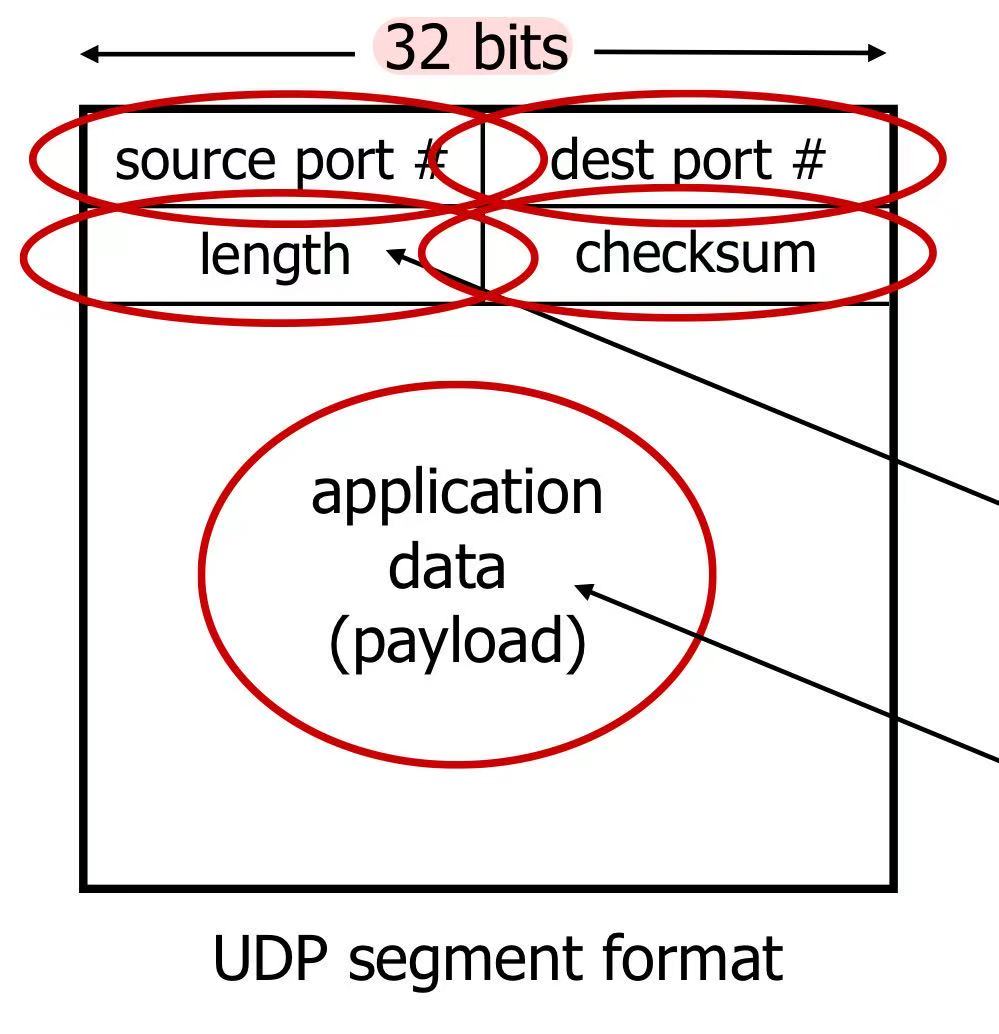
Internet Checksum
- sender: treat contents of UDP segment (including UDP header fields and IP addresses) as sequence of 16-bit int, add them. if carry, add the carry-bit to the end. repeat it tow by two (this one with last result). then negate the final output to be the ‘checksum’
- receiver: repeat it and add the result to the check sum. if all 1, check √ (but may also have errors)
2.5 Transport Layer Protocol: TCP (Transmission Control Protocol)
2.5.1 TCP Segment Structure
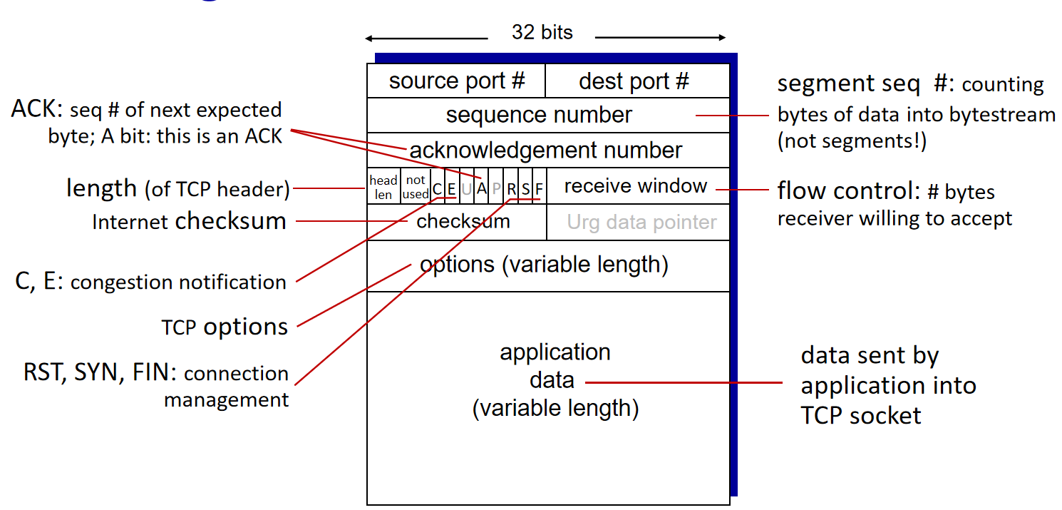
- Sequence numbers are assigned to bytes in the data stream.
- Acknowledgment numbers represent the
next expected byte.
2.5.2 Round-Trip Time Estimation and Timeout in TCP
Round-Trip Time Estimation:
TCP calculates an average RTT,EstimatedRTTofSampleRTT, using an exponentially weighted moving average (EWMA) formula:- typical value of alpha is 0.125.
RTT Variation Measurement:
TCP also measures RTT variation (
DevRTT) to estimate how much SampleRTT deviates from EstimatedRTT.DevRTT is calculated as an EWMA of the difference between
SampleRTTandEstimatedRTT.typiclly, beta = 0.25
Setting the Retransmission Timeout Interval:
- DevRTT plays a role in determining the timeout interval:
2.5.3 Reliable Data Transfer
Timeout and Retransmission Handling:
- arrival of in-order segment with expected sequence number
- no waiting: delayed ACK, wait some time and send
- waiting packets exist: immediately send cumulative ACK, ACKing both in-order segments
- arrival of out-of-oder segment with higher-than-expected sequence number: immediately send duplicate ACK, indicating sequence number of next expected byte
- arrival of segment that partially or completely fills in gap in received data: immediately send ACK, provided that segment starts at the lower end of gap
- arrival of in-order segment with expected sequence number
TCP Fast Retransmit:
- If the TCP sender receives three duplicate ACKs for the same data, it performs a
fast retransmitretransmitting the missing segment before that segment’s timer expires.
- If the TCP sender receives three duplicate ACKs for the same data, it performs a
2.5.4 Flow Control
Animation: Flow Control
TCP Flow Control ensures that the sender doesn’t overwhelm the receiver’s buffer.
Flow Control vs. Congestion Control:
- Flow control matches sender rate to receiver reading speed.
- Congestion control manages sender rate due to network congestion.
- Although they both throttle the sender, they serve different purposes.
TCP Flow Control: TCP receiver “advertises” free buffer space in rwnd field in TCP header
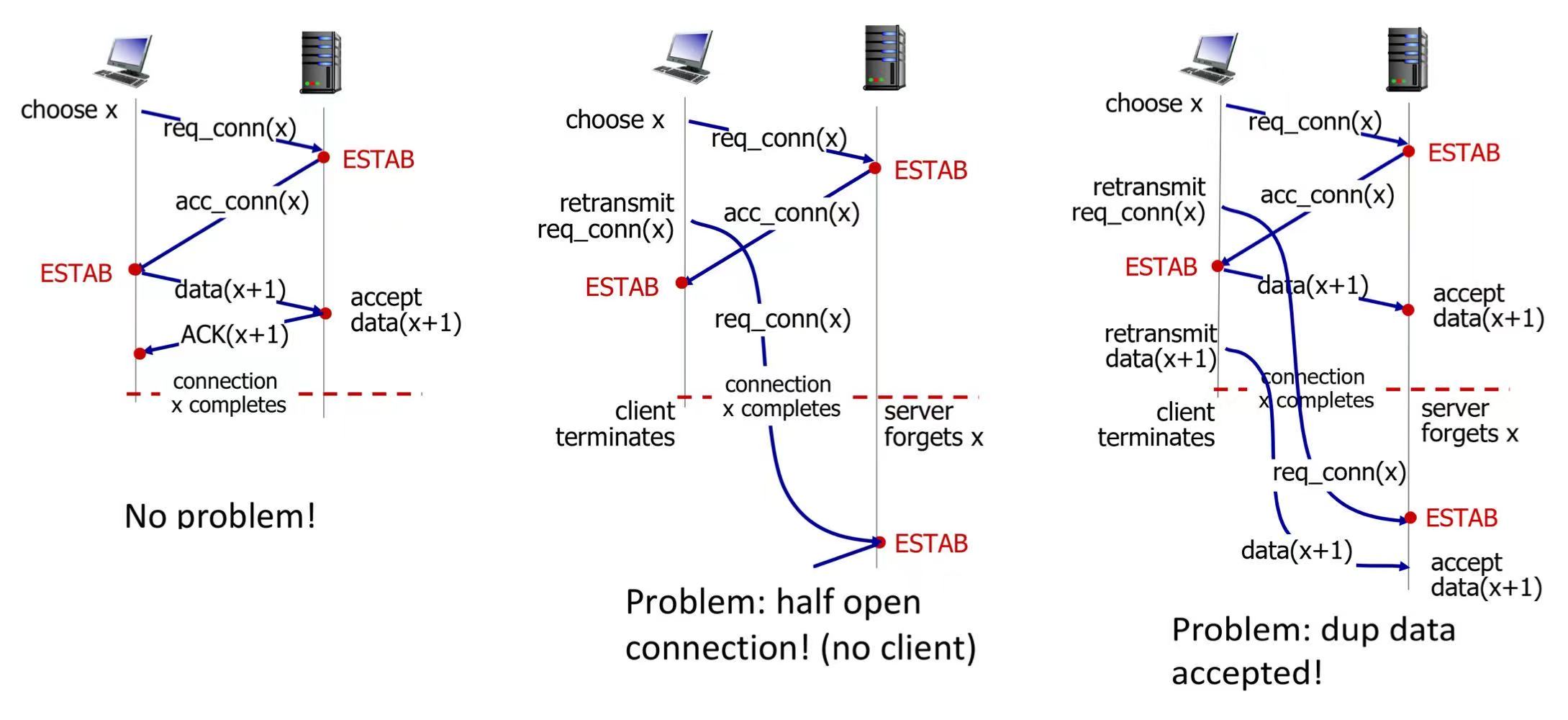
2.5.5 TCP Connection Management
2-way handshake: may suffer half open connection or dup data accepted problems
3-way handshake:
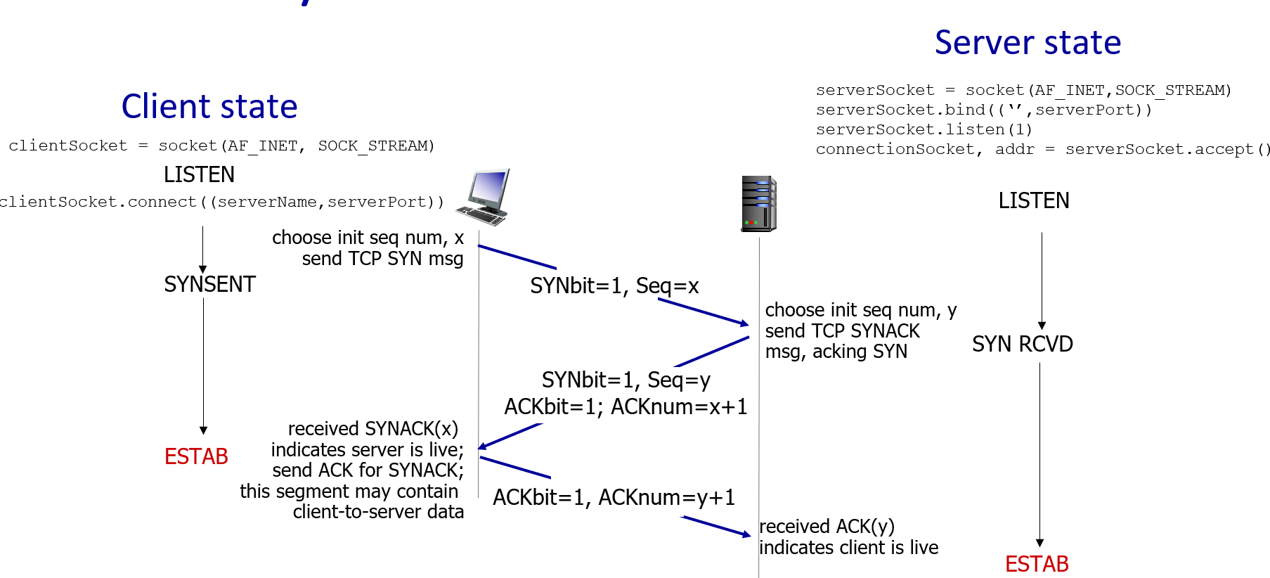
- first and second msg with SYN=1, while the third msg with SYN=0
- server only allocates resources after receiving the third ACK, and unfinished connections do not occupy resources
closing a TCP connection:
- client, server each close their side of connection. send TCP segment with FIN bit = 1
- respond to recerived FIN with ACK
2.5.6 TCP Congestion Control
loss based control, defined as either a timeout or three duplicate ACKs.
Slow Start, quick ramp up:
- cwnd starts at 1 MSS, and doubles after each successful RTT.
- done by incrementing cwnd for every ACK received
Congestion Avoidance:
- Start when cwnd reaches ssthresh (1/2 of its value before timeout)
- Linear increase of cwnd by 1 MSS per round = typical AIMD
versions:
TCP Tahoe: Cut to 1 MSS (maximum segment size) when loss detected by timeout
TCP Reno: Cut in half on loss detected by triple duplicate ACK
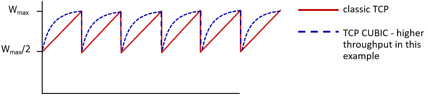
TCP CUBIC: after cutting rate/window in half on loss, initially ramp to to Wmax faster, but then approach Wmax more slowly

Chapter 3: Network Layer
Network layer’s primary role is to move packets from a sending host to a receiving host.
3.1 two switch idea
3.1.1 Circuit Switching
- reserve resources for the entire communication session. (so no need to forward or routing)
- frequency division multiplexing (FDM) or time division multiplexing (TDM).
3.1.2 Packet Switching
hosts break message into smaller chunks, known as packets, as well as transmit packet into access network.
Most packet switches use store and forward transmission: must receive the entire packet before transmission.
Packet Delay

- within the router
Processing Delay Part of the processing delay includes examining the packet’s header and checking for bit level errors. in microseconds.
Queuing Delay occurs as packets wait in a queue before being transmitted onto the link. range from microseconds to milliseconds. most unstable and can’t be predicted.
Transmission Delay It is the time required to push all of a packet’s bits into the link. typically in microseconds to milliseconds.
- else
- Propagation Delay time for a bit to propagate from one router to the next, dependent on the distance between routers and the propagation speed of the link. in milliseconds for wide area networks.

Packet Loss
- happen when the buffer is full due to congestion or near full as a warning (TCP).
- retransmitted by previous node, by source end sysytem, or not at all (UDP).
Trace Route: sends three packets that will reach router i on path towards destination and measures time interval between transmission and reply
key functions
- Forwarding: router-local action of transferring a packet from an input link interface to the appropriate output link interface. (Data plane)
- Routing: determines the end-to-end paths that packets take from source to destination.
3.2 Packet Switch - Forwarding
3.2.1 Router
Components of a Generic Router:

- input port, switch fabric, output port; routing processor
1. Input Port Functions
- destination-based forwarding: forward based only on destination IP address (traditional)
- generalized forwarding: forward based on any set of header field values
- Checking packet’s version number, checksum, and time-to-live field.
Longest Prefix Matching
when looking for forwarding table entry for given destination address, use longest address prefix that matches destination address.
It is equivalent to performing an exclusion. An example is large-scale mobile number portability.
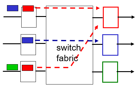
Input Port Queuing
- happens when switch fabric slower than input ports combined
- Head-of-the-Line (HOL) blocking:
2. Switch Fabric
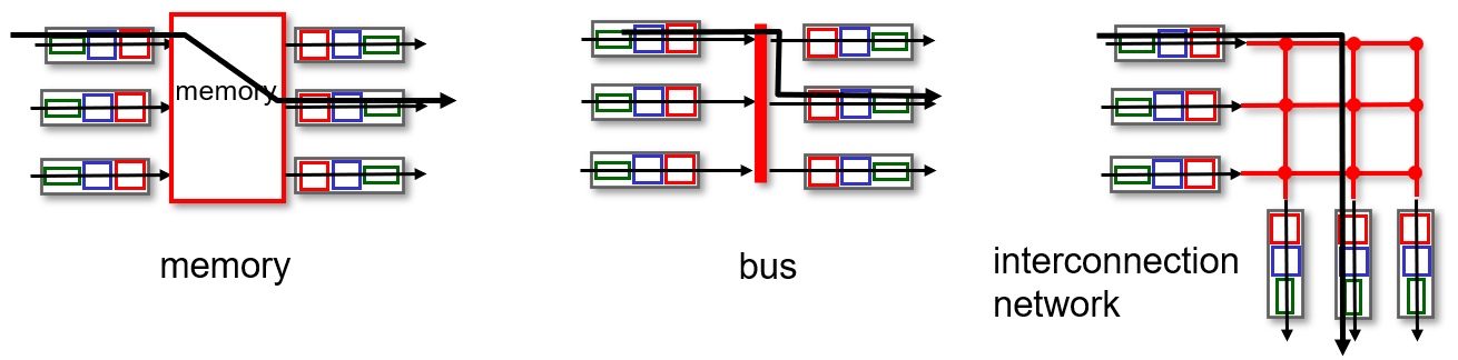
Memory:
- Packets copied into processor memory, and the CPU handled destination address lookup and forwarding table processing.
- Limited by memory bandwidth.
Bus:
- Limited by bus speed; only one packet can cross the bus at a time.
- Common in small local area and enterprise networks.
Interconnection Network:
- multistage switch: nxn switch from multiple stages of smaller switches.
3. Output Port Processing
Output Queueing
- happens when datagrams arrive from fabric faster than link transmission rate.
- Queued packets can overwhelm the output port’s memory -> packet loss.
Buffering Management
- too much buffering can increase delays
- Traditional rule: Buffering (B) equals average round-trip time (RTT) times link capacity (C), i.e., $B = RTT * C$.
- more recent recommendation: with N flows, $ B = \frac{RTT * C}{\sqrt{N}}$ (With more flows (N), traffic becomes smoother due to statistical multiplexing—independent flows rarely sync their bursts.)
- buffer drop: tail drop or priority
- marking: which packets to mark to signal congestion (ECN, RED)
Router and MAC Address
- When a router determines the outgoing interface, it still needs to use its local ARP table to map the next-hop IP address to a MAC address.
- This is because the data link layer only understands MAC addresses, not IP addresses. And Ethernet frame needs it.
The output port may connect to multiple routers or switches, so it cannot “hardcode” one MAC. Only in point-to-point or non-Ethernet links (like SDH or MPLS over MPLS), MAC resolution might be unnecessary.
4. Packet Scheduling
| Discipline | Description |
|---|---|
| FIFO | First in first out |
| Priority Queuing | Classifies packets into priority classes; higher-priority packets first. |
| Round Robin | classified packets, sending one complete packet from each class (if available) in turn. |
| Weighted Fair Queuing | Generalized round robin with differential service based on weights assigned to each class. minimum bandwidth guarantee (per-traffic-class) |
other thing
- interface: connection between host/router and physical link
- router’s typically have multiple interfaces (with lots of network cards on it)
- host typically has one or two (e.g., wired Ethernet, wireless 802.11)
5. Multiprotocol Label Switching (MPLS)
- enhances IP router’s forwarding speed by
fixed-length labels.- look up labels in their forwarding tables, eliminating the need to extract IP addresses for routing decisions.
- No longer need to traverse to determine whether the current match is the longest match.
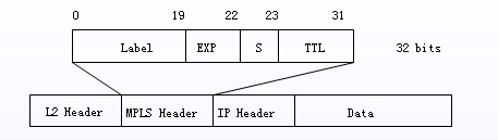
(exp - priority)
flexibility: MPLS forwarding decisions can differ from those of IP
entry MPLS router uses RSVP-TE signaling protocol to set up MPLS forwarding at downstream routers
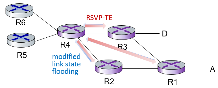
- MPLS remember two routes: formal and backup routes in case of link failure
- IP router only remember the output interface
- MPLS remember two routes: formal and backup routes in case of link failure
modify: use OSPF, IS-IS link-state flooding protocols to carry info used by MPLS routing:
- e.g., link bandwidth, amount of “reserved” link bandwidth
a process: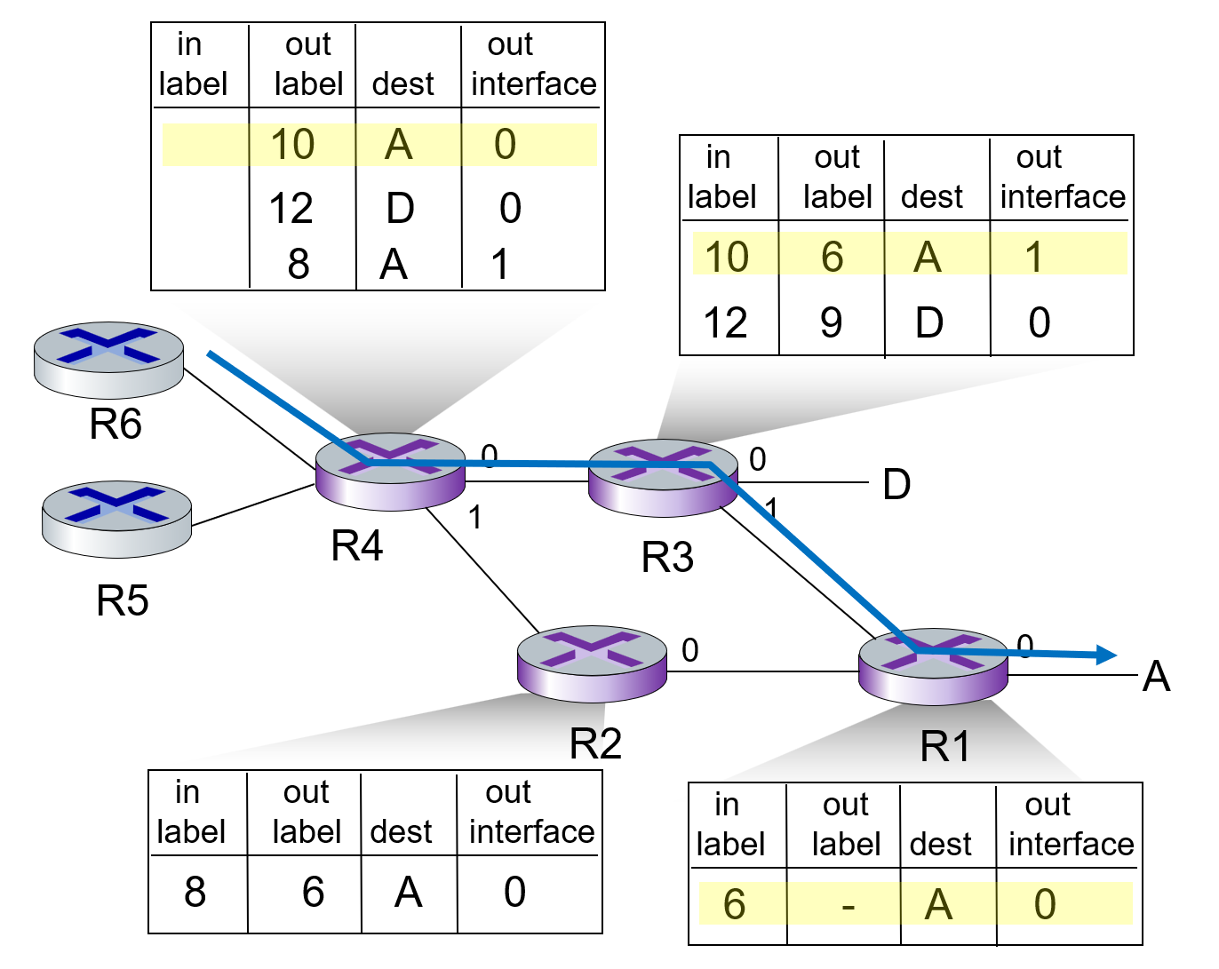
在 setup 过程中各自确认出入label而不是使用一个统一label
3.2.2 Network Layer Protocol: IP
1. something to know
- dotted-decimal IP address notation: 233.1.1.1 = 11011111 00000001 00000001 00000001.
- subnet: device interfaces that can physically reach each other without passing through an intervening router (but can connected by a switch)
- devices in same subnet have common high order bits.
- 233.1.1.0/24 means they share the fixed 24 bits of the address(which is 233.1.1) and the remaining 8 bits are variable.
- counting method: detach each interface from its host of router. count islands of isolated networks
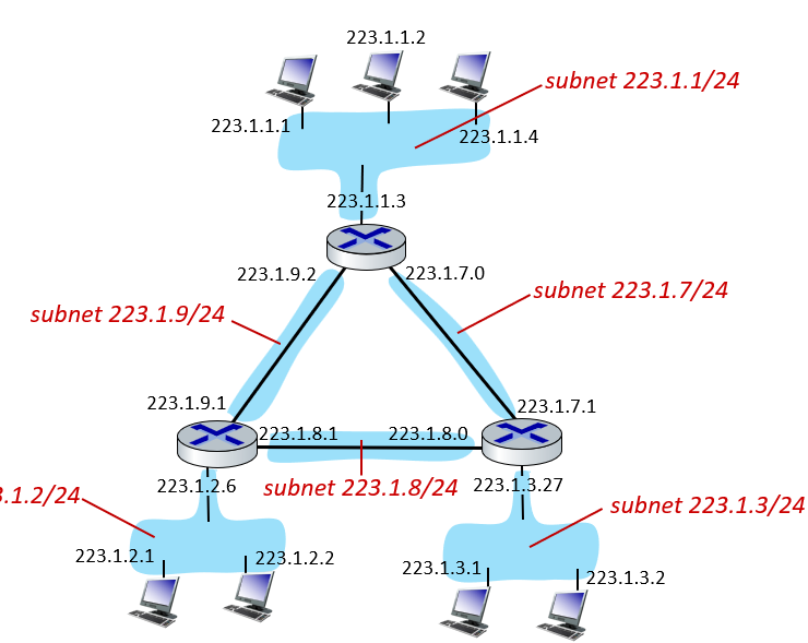
- devices in same subnet have common high order bits.
CIDR (Classless InterDomain Routing)
- class interdomain routing: /x. x = 8n
- classless: subnet portion of address of arbitrary length
IP Address Aquisition
Dynamic Host Configuration Protocol (DHCP)
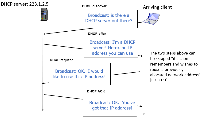
- DHCP can return more than just allocated IP address on subnet:
- address of first-hop router for client
- name and IP address of DNS sever
- network mask
- DHCP REQUEST msg encapsulated in UDP; in IP; in Ethernet
- DHCP can return more than just allocated IP address on subnet:
subnet part aquisition
gets allocated portion of its provider ISP’s address space
Hierarchical addressing: route aggregation and “number portability”
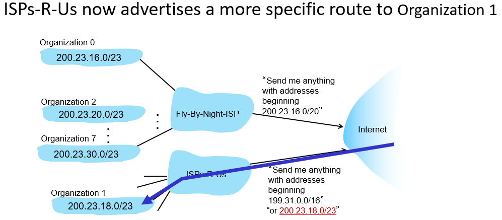
and this is also why the longest match is used in routing table lookup.
2. IPv4
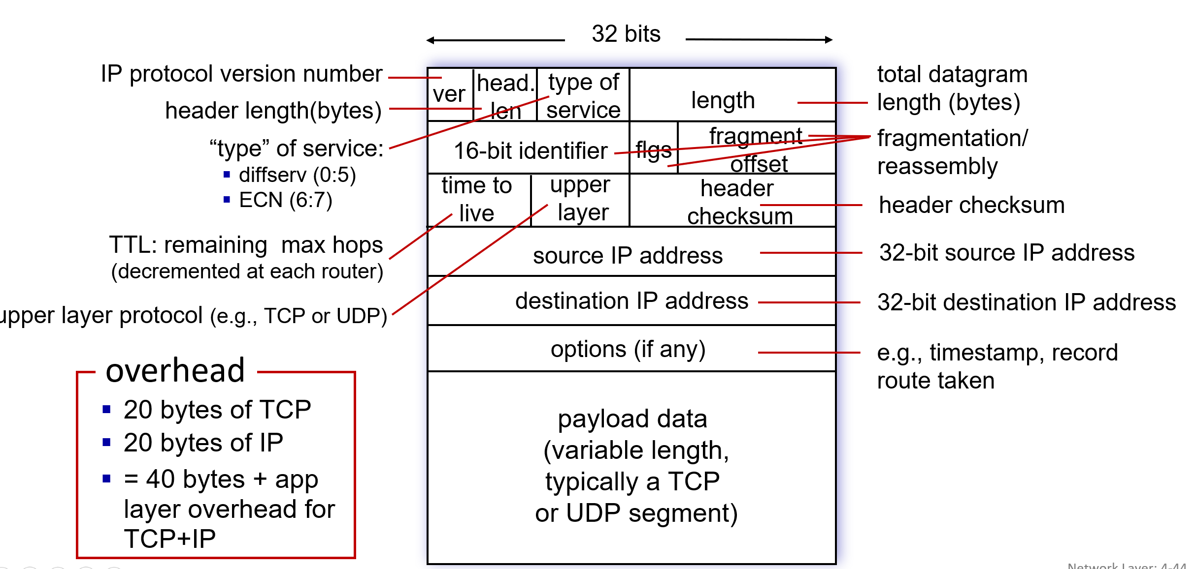
- fragmentation/reassembly: large datagrams are broken into smaller fragments for transmission.
- 32-bit IP address
- because TTL is updated in every router passed, so header checksum will be recalculated per router
Note: An IP datagram typically has a 20-byte header (excluding options). If carrying a TCP segment, each datagram includes a total of 40 bytes of header (20 + 20).
- use ARP
3. IPv6
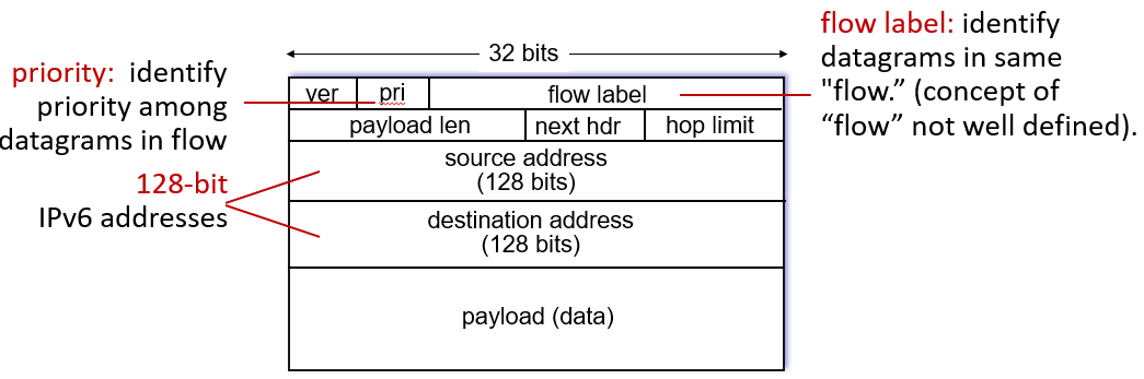
compared with IPv4: no checksum, fragmentation/reassemblly, options. longer header. use NDP (instead of ARP)
4. from IPv4 to IPv6
tmp: Network Address Translation (NAT)
all devices in local network (LAN side) share one IPv4 address as far as outside world (WAN side) is concerned, while port numbers differ.
a translation will happen at NAT routers when packets enter or leave the local network. NAT router has a translation table.
- change the source IP and port number
advantages:
- Only one public IP needed
- Internal addresses can change freely
- ISP change doesn’t affect local devices
- Adds security (internal devices hidden)
conflict solve: tunneling
- not all routers can be upgraded simultaneously into IPv6 - no “flag days”
- tunneling: IPv6 datagram carried as payload in IPv4 datagram among IPv4 routers

3.2.3 Generalized Forwarding
- OpenFlow abstraction: match bits in arriving packet header(s) in any layers, take action
- matching over many fields (link-, network-, transport-layer)
- local actions: drop, forward, modify, or send matched packet to controller
- following 4 are unified under OpenFlow abstraction
| Device | Match | Action |
|---|---|---|
| Router | Longest destination IP prefix | Forward out a link |
| Switch | Destination MAC address | Forward or flood |
| Firewall | IP addresses and TCP/UDP port numbers | Permit or deny |
| NAT | IP address and port | Rewrite address and port |
3.3 Packet Switch - Routing
- Two approaches to structuring network control plane:
- per-router control (traditional)
- logically centralized control (software defined networking)
3.3.1 Routing Algorithms
1. link-state routing
- centralized: network topology, link costs known to all nodes
- computes least cost paths from one node (“source”) to all other nodes, iteration ++ -> known path ++
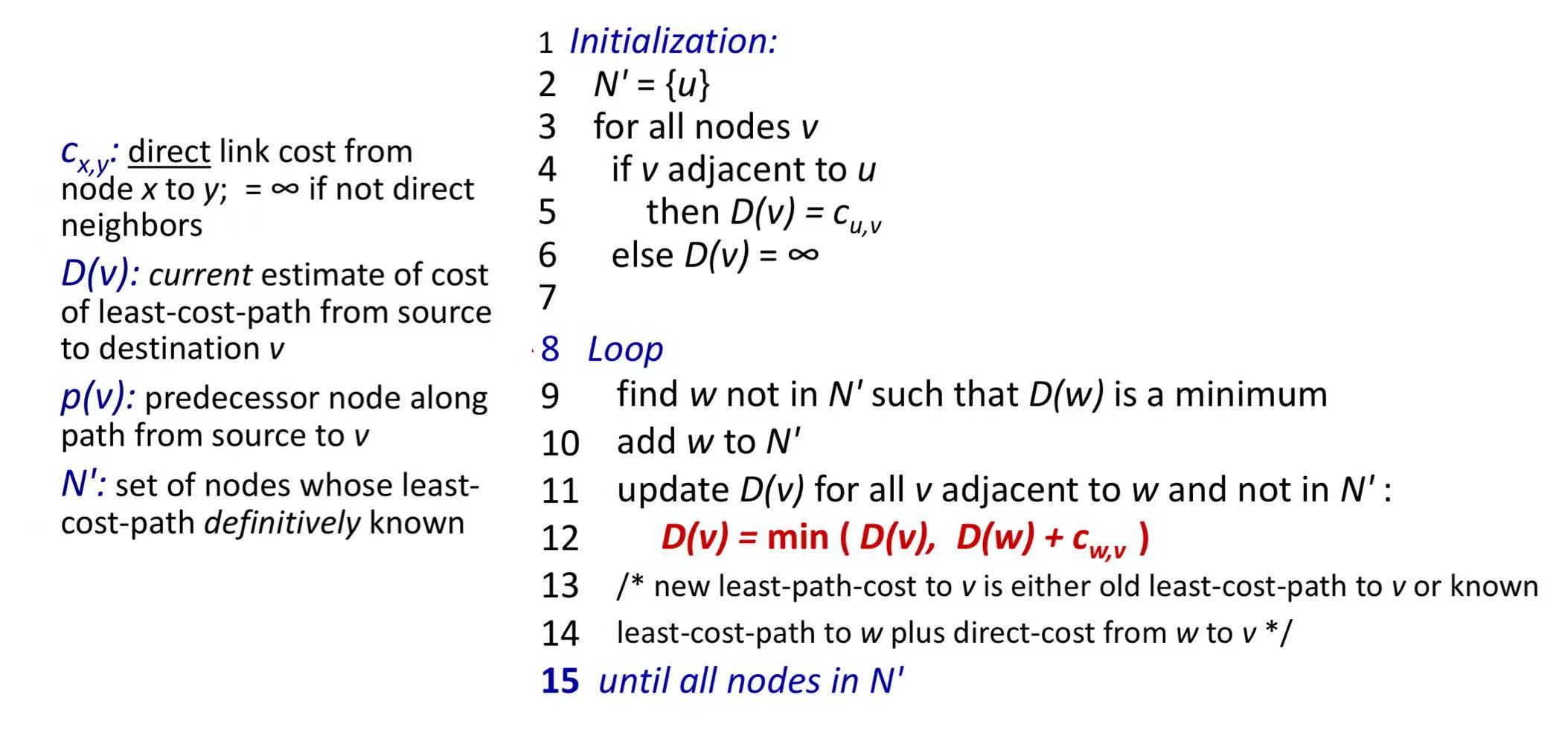
how do they know the initial nerghbors’ costs? by flooding!
results a least-cost-path tree from u -> forwarding table in u.
algorithm complexity: $O(n^2)$, message complexity: $O(n^2)$
drawback: possible oscillations. e.g.
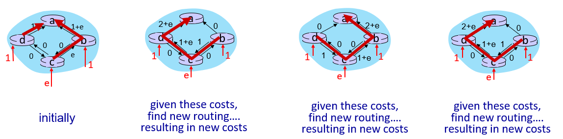
(if link costs/weights depend on volume of traffic)
2. Distance-vector routing
Basis: Bellman-Ford equation: ( D_x(y) = \min_v { c_{x,v} + D_v(y) })
- v are neighbors. c is direct cost. D is neighbor’s distance to destination.
- can solve negative link weights problem (but negative circle X)
key ideas:
- from time-to-time, each node sends its own distance vector estimate to neighbors (if changing, immediately notify neighbors)
- when receiving distance vectors, node updates its own DV using B-F equation
- under minor, natural conditions, the estimate Dx(y) converge to the actual least cost dx(y)
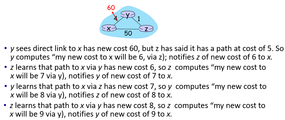
drawback: good news (decrease) trevels fast. bad news (increase) travels slow (count-to-infinity problem). e.g.
black-holing: DV router can advertise incorrect path cost (“I have a really low-cost path to everywhere”) to capture all the messages
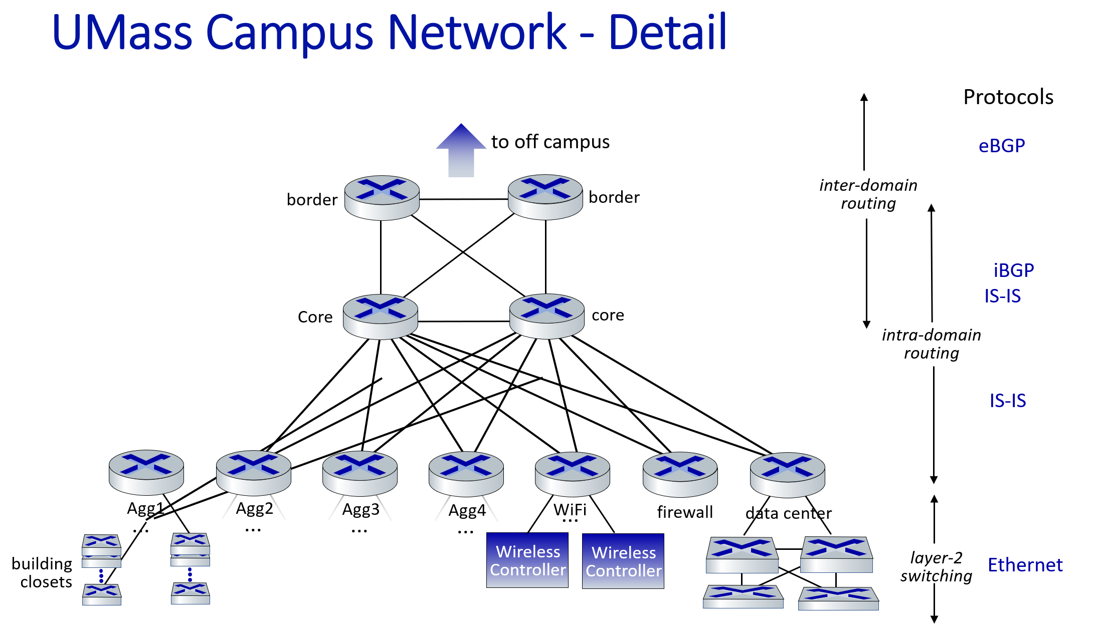
3.3.2 Intra-AS Routing
something to know
ASs: Routers organized into Autonomous Systems (ASs, a.k.a. “donmains”), each under the same administrative control, deploy same routing algo. and know info. of each ohters
IGP (Interior Gateway Protocol) is a type of routing protocol used within AS to determine the best path for data packet transmission.
- include RIP, OSPF, IS-IS
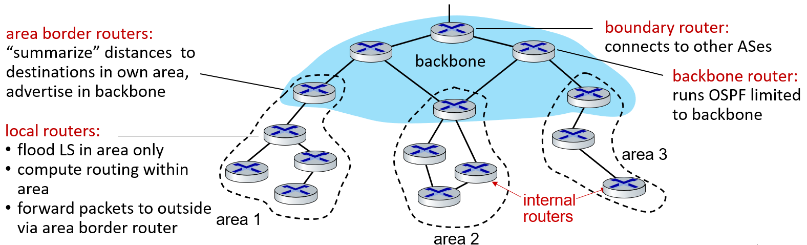
OSPF (Open Shortest Path First)
link-state routing: each router has full topology, uses Dijkstra’s algorithm to compute forwarding table
- each router floods OSPF link-state advertisements in entire AS
security: all OSPF messages authenticated
hierarchical: local area and backbone
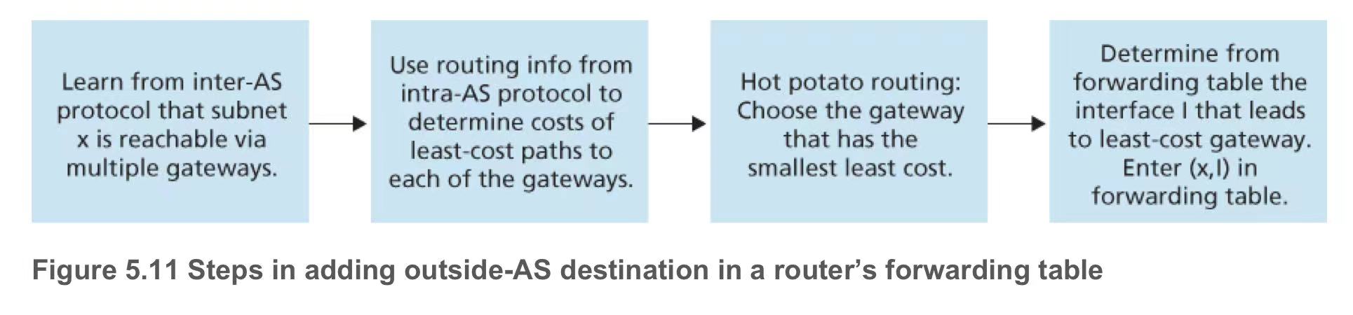
3.3.3 Inter-AS Routing: BGP
- BGP = Border Gateway Protocol
- exchange BGP msg over semi-permanent TCP connection.
- suffer route hijacking
functions
- obtain destination network reachability info from neighboring ASs (eBGP)
- determine routes to other networks based on reachability information and policy
- propagate reachability information to all AS-internal routers (iBGP)
- advertise (to neighboring networks) destination reachability info (alternative)
- to be noticed, border router may accept/decline path (advertisements from other ASes. e.g. (AS2, AS3, X) vs (AS2, X), choose second one), then advertise them within AS
routing algo.
router advertises route (prefix + attributes) when entering BGP networks or BGP info update
- prefix: destination network address
- BGP Attributes:
AS-PATH: List of ASs through which the advertisement has passed.NEXT-HOP: indicates specific internal-AS router to next-hop AS.- (so also known as path vector protocol)
each router will only remember the destination can be reached and the interface to push packets on to reach them(forwarding table)policy based route selection:
- local preference value attribute: policy decision
- shortest AS-PATH
- Hot Potato Routing: get packets out of an Autonomous System (AS) quickly with minimal cost (each road has a cost)
- additional criteria
3.3.4 SDN (Software defined networking)
monolithic router contains switching hardware, runs proprietary implementation of Internet standard protocols (IP, RIP, IS-IS, OSPF, BGP) in proprietary router OS (e.g., Cisco IOS)
differences with convetion
- Distributed vs logically centralized
- easier network management
- Dest IP based forwarding vs source routing
- Single path vs multiple possible paths
- traffic engineering: separate a huge data stream into smaller streams and send them through different paths (maybe by re-defining link weights or change the tables - won’t change algo.)
- Distributed vs logically centralized
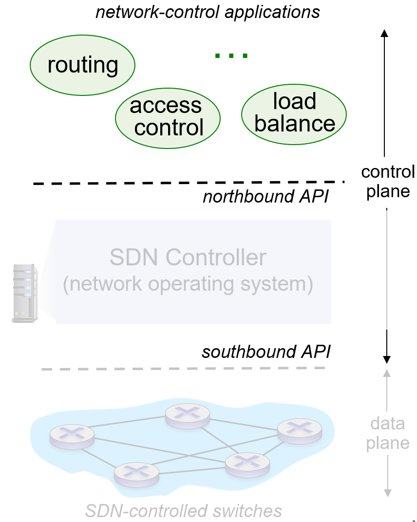
(northbound API is about applications , southbound API is about SDN-controlled swithces)
OpenFlow protocol
- operates between controller, switch
- TCP used
- three kind of messages:
- controller-to-switch: features, configurations, modify-state, packeer-out
- switch-to-controller: packet-in, flow-removed, port status
- symmetric (misc.)
three controllers
- OpenDaylight (ODL)
- Google ORION: iGBP (intradomain serices within Google’s network), edge-edge flow-based, management
- ONOS: control apps separate from contriller
3.3.5 ICMP (Internet Control Message Protocol)
- used by hosts and routers to communicate network-level information.
- error reporting, echo request/reply, traceroute, etc.
- carried in IP datagrams
Chapter 4: Data Link Layer
4.1 an overview
- transports datagram from one node to physically adjacent node over a link.
- includes protocols like Ethernet, Wi-Fi and ARP, managing tasks like framing, link access (MAC), reliable delivery, and error detection/correction.
- framing: add header,
tailer. MAC addresses in frame headers identify source, destination
- framing: add header,
- implemented on a chip called the network adapter or
network interface controller (NIC).- attached into host’s system buses
- differnet link protocols over different links
- has flow control
4.2 Error Detection & Correction Techniques
- EDC: error detection and correction bits
- D: data protected by error checking
4.2.1 Parity Check
- Even Parity: Ensures that the total number of 1 in a data unit (including the parity bit) is even.
- If an odd number of bits are in error, the parity check will detect it.
- Odd Parity
- 2D Parity Check
- apply parity check to each row and column of bits
- detect and correct single-bit errors.
4.2.2 Internet Checksum
- the same as introduction in Chapter 3
- 16bits. add. carry. negate.
4.2.3 Cyclic Redundancy Check (CRC)
- D = data bits, G = bit pattern (of r+1 bits, specified in CRC standard)
- <D, R> = D*$2^r$ XOR R is exactly divisible by G
- can detect burst errors (consecutive bit errors) <= r bits
- caculation of R: ( R = \text{remainder} \left[ \frac{D \cdot 2^r}{G} \right] ) 注意:中间不是减法,是异或!(模二除法)
4.3 Multiple Access Protocols
- two or more simultaneous transmissions by nodes: interference -> collision
- communication about channel sharing must use channel itself!
- no out-of-band channel for coordination
4.3.1 Channel Partitioning Protocols
- TDMA: time division multiple access
- each node gets a fixed time slot to transmit
- FDMA: frequency division multiple access
- each node gets a fixed frequency band
CDMA (Code Division Multiple Access)
unique “code” assigned to each user
allows simultaneous transmit (if codes are “orthogonal”)
method:
- encoding: inner product: (original data) X (chipping sequence)
- decoding: summed inner-product: (encoded data) X (chipping sequence)
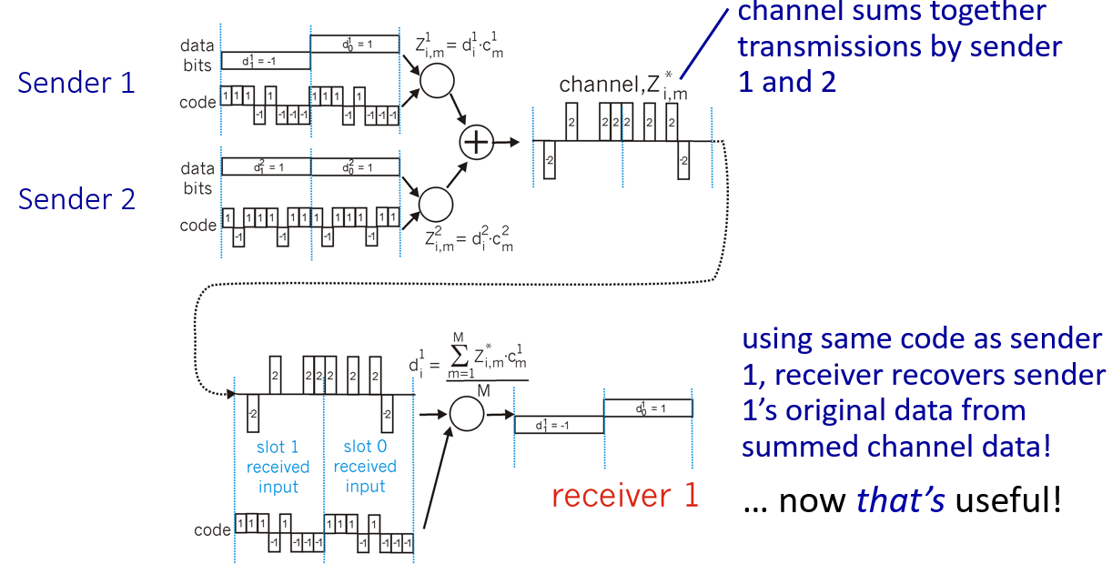
每次实际传的是一位bit的码扩展,能恢复出一位数据;内积得到的符号就是要传输的信息,-1映射到二进制中的0
4.3.2 Random Access Protocols
- when node has packet to send, it transmits immediately.
- protocols define
- how to detect collisions
- how to recover from collisions
- examples: ALOHA, slotted ALOHA, CSMA, CSMA/CD, CSMA/CA
1. Pure ALOHA
- Nodes immediately transmit frames into the channel and waits for acknowledgement.
- If ACK not received, node waits for random backoff time and re-sends data.
- If a collision occurs, nodes retransmit with a probability.
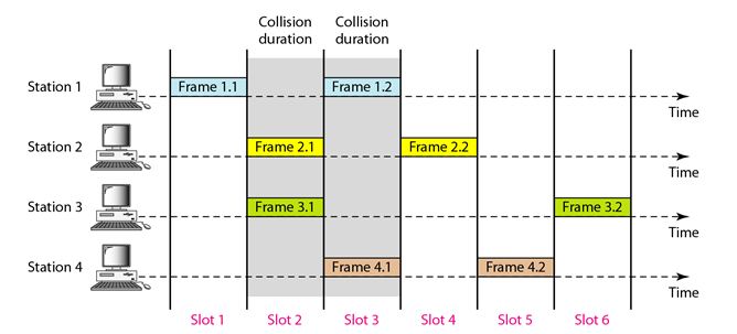
2. Slotted ALOHA
- time is divided into time-slots.
- Nodes are allowed to transmit at slot beginnings. Collisions are detected, and nodes retransmit with a probability.
- efficiency: 1/e = 36.8%
suppose: N nodes with many frames to send, each transmits in slot with probability p
• prob that given node has success in a slot = (p(1-p)^{N-1})
• prob that any node has a success = (Np(1-p)^{N-1})
• max efficiency: find (p^) that maximizes (Np(1-p)^{N-1})
• for many nodes, take limit of (Np^(1-p^)^{N-1}) as N goes to infinity, gives: (p^ = 1/e) = 36.8%
3. Carrier Sense Multiple Access (CSMA)
- listen before transmitting
- if channel is idle, transmit; if busy, wait and try again
4. CSMA/CD
- CSMA + collision detection (easy in wired, difficult in wireless) ~ used in Ethernet
- collision happens because of propagation delay
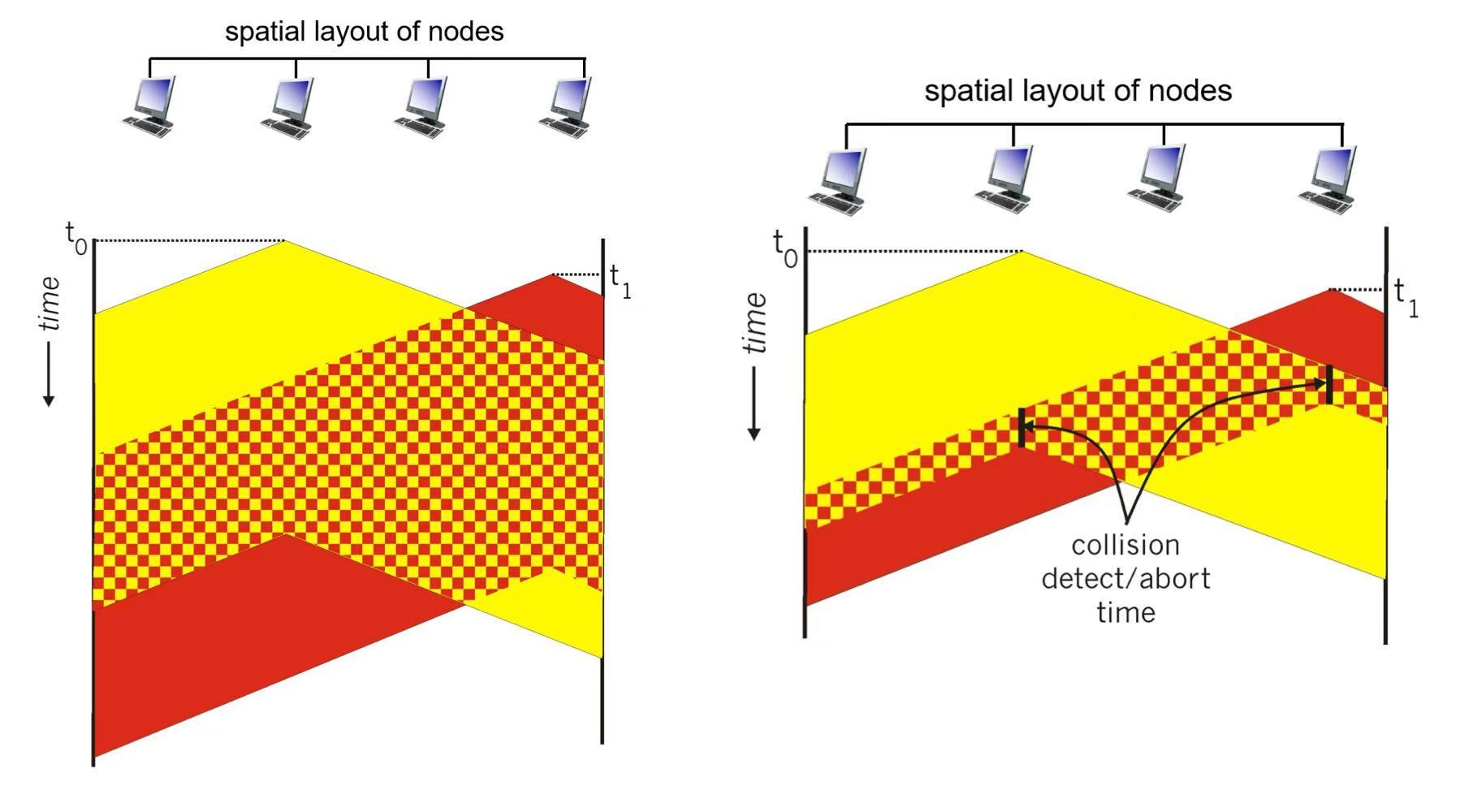
transmission aborted on collision detection
- After aborting, enter binary (exponential) backoff:
- after mth collision, chooses K at random from ${0,1,2, …, 2^m-1}$. Ethernet waits K·512 bits’ transmission time, then re-listen
efficiency: $\frac{1}{1 + 5 \frac{t_{prop}}{t_{tran}}}$, $t_{prob}$ is max propagation delay between 2 nodes in LAN, $t_{tran}$ is time to transmit max size frame ~ experience formula
5. CSMA/CA
CA = Collision Avoidance
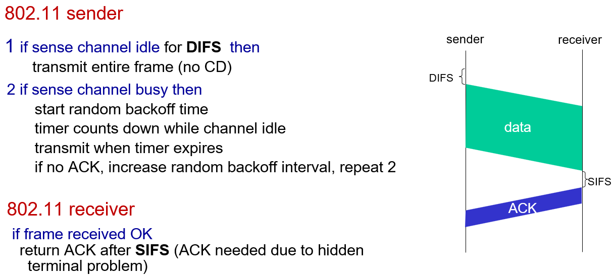
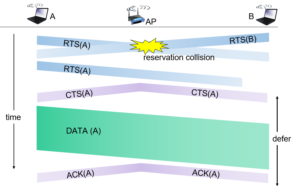
sender “reserves” channel use for data frames using small reservation packets
- sender first transmits small request-to-send (RTS) packet to BS (Base Station) using CSMA (RTSs may still collide with each other)
- BS broadcasts clear-to-send CTS in response to RTS
- CTS heard by all nodes. sender transmits data frame, other stations defer transmissions
in this mechanism, a sender who just finished a transmission is at a better position of successfully issuing the nesxt RTS message
4.3.3 Taking Turns Protocols (Controlled Access)
- usage: Bluetooth, FDDI, token ring
- pooling: centralized controller “invites” other nodes to transmit in turn
- Bluetooth uses polling
- token passing: token is passed around the LAN, and only node with token can transmit
4.4 Data Link Layer Addressing
4.4.1 Media Access Control (MAC) Addresses
- alias: LAN / physical / Ethernet address
- function: used “locally” to get frame from one interface to another physically-connected interface (same subnet, in IP-addressing sense)
- always 48-bit, e.g. 1A-2F-BB-76-09-AD
- portable: can move interface from one LAN to another (vs IP: depends on IP subnet to which node is attached)
Why do we still need IP addresses? Why not just use MAC addresses?
| Problem | MAC Address Limitation | IP Address Solution |
|---|---|---|
| No hierarchy | MACs are hardcoded by manufacturers and don’t reflect network topology | IPs are hierarchical and can be subnetted |
| Cannot communicate across networks | MACs are only valid within a local broadcast domain | IPs are globally routable across the Internet |
| No dynamic addressing | MACs are static and difficult to reassign | IPs can be assigned dynamically via DHCP or NAT |
| Broadcast storm risk | Switches flood unknown MACs, leading to high broadcast traffic | Routers isolate broadcast domains using IP |
| Poor scalability | Flat MAC space causes large, unstructured tables | IPs can be aggregated using CIDR to scale efficiently |
- Quick Analogy
- MAC address ≈ ID number (fixed identity)
- IP address ≈ Mailing address (location-based and hierarchical)
4.4.2 Address Resolution Protocol (ARP)
- resolves IP addresses to MAC addresses
- Hosts and routers maintain ARP tables with entries <IP address, MAC address, TTL>.
- action:
- A wants to send datagram to B with only IP address:
- A broadcasts (destination MAC address = FF:FF:FF:FF:FF:FF) ARP query containing B’s IP address. Then B returns its MAC address. A records this mapping in its ARP table.
- routing to another subnet (sending a datagram from A to B via R)
- A knows B’s IP address (maybe by DNS); IP address of first hop router R and R’s MAC address (DHCP).
- R will change the source MAC from A to R, and destination MAC from R to B.
- source and destination IP address keep the while journey, while every hop is with 2 MAC address changes
- A wants to send datagram to B with only IP address:
4.4.3 hardware: Switches
- plug-and-play: no need to configure
- helps reduce collisions (but one out/in line can only transmit one frame at a time), increase bandwidth, and improve performance
- when frame received at switch:
- record incoming link, MAC address of sending host (self learning)
- index switch table using MAC destination address
if entry found for destination, then
- if destination on segment from which frame arrived (e.g. 多级结构中下层比上层先忘记)
- then drop frame
- else forward frame on interface indicated by entry
- if destination on segment from which frame arrived (e.g. 多级结构中下层比上层先忘记)
else flood /* forward on all interfaces except arriving interface */
switches vs routers
- both are store-and-forward:
- routers: network-layer devices (examine network-layer headers)
- switches: link-layer
- both have forwarding tables:
- routers: compute tables using routing algorithms; IP addresses
- switches: learn forwarding table using flooding, self-learning; MAC addresses
4.5 Ethernet
- physical topology: bus or switched (main)
- ehthernet frame structure:
- preamble: used to synchronize receiver clock with sender clock
- destination MAC address & source MAC address, 6 bytes each
- type: 2 bytes, indicates higher layer protocol
- data (payload)
- CRC: cyclic redundancy check at receiver
- connectionless: no handshaking and unreliable delivery
4.5.1 Virtual Local Area Networks (VLANs)
- switches supporting VLAN capabilities can be configured to define multiple virtual LANS over single physical LAN infrastructure
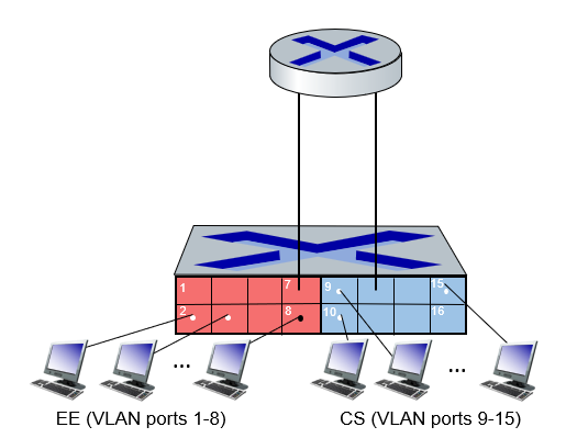
- In a port-based VLAN (like above),
- traffic isolation: frames to/from ports 1-8 can only reach ports 1-8
- dynamic membership: ports can be dynamically assigned among VLANs
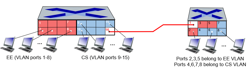
trunk port: carries frames between VLANS defined over multiple physical switches
above is 802.1 Ethernet frame, below is 802.1Q frame (VLAN frame format)

EVPN (Ethernet VPNs, aka VXLANs)
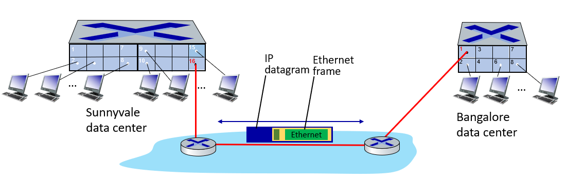
- Ethernet switched logically connected to each other (e.g., using IP as an underlay)
- tunneling scheme to overlay Layer 2 networks on top of Layer 3 networks
4.6 Wireless Networks
4.6.1 something to know
- elements: wireless hosts, base station (typiclly connected to wired network), wireless link
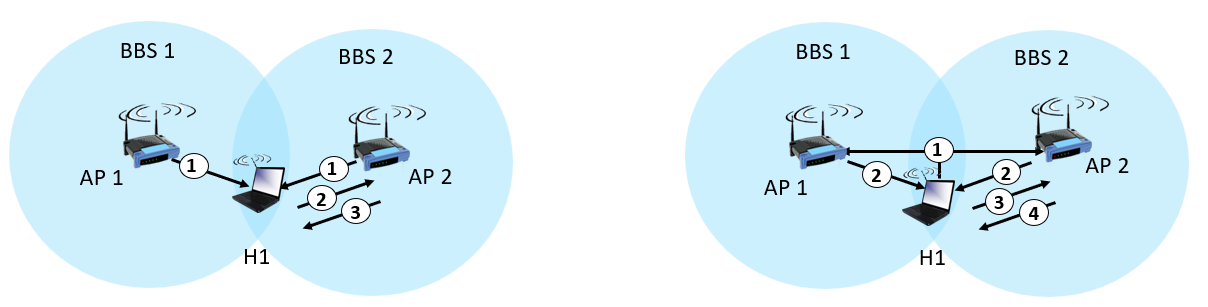
- infrastructure mode: base station connnects mobiles into wired network
- Basic Service Set (a.k.a. cell) contains: wireless hosts + access point (AP)
- ad hoc mode: no base stations, nodes route among themselves
- infrastructure mode: base station connnects mobiles into wired network
wireless link characteristics :
radio signal attenuates as it propagates
- $\text{Free space path loss} \sim (fd)^2$
multipath fading: radio signal reflects off objects ground, built environment, arriving at destination at slightly different times
noise: interference from other sources
- SNR: signal-to-noise ratio: larger, the easier to extract info from noise
- increase power -> increase SNR + decrease BER (Basic Error Rate)
hidden terminals: caused by obstruction or attenuation
- solution: RTS-CTS-DATA-ACK (CSMA/CA)
- exposed terminal problem: a node refrains from transmitting to another node due to detecting a signal from a nearby node, even though such transmission would not cause interference
Key challenges:
- Signal attenuation occurs too quickly
- Interference from other signals
- Self-interference caused by signal reflection
- Rapidly changing network topology due to high mobility
4.6.2 WiFi
all versions use CSMA/CA for multiple access
arriving host: must associate with an AP
scans channels, listening for beacon frames containing AP’s name (SSID) and MAC address
- passive/active scanning:
- passive/active scanning:
selects AP to associate (by the power)
then typically run DHCP to get IP address in AP’s subnet
frame: addressing
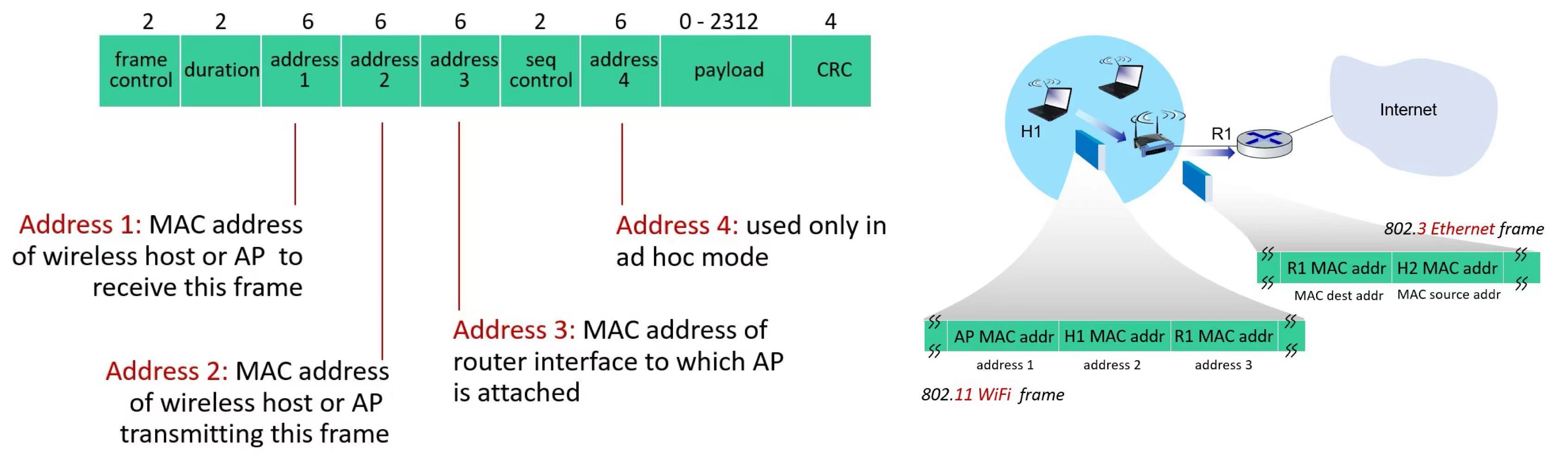
(duration = duration of reserved transmission time (RTS/CTS))
- OFDM
4.6.3 Cellular networks: 4G and 5G
- 4G: Long-Term Evolution (LTE) standard
- OFDM: Orthogonal Frequency Division Multiplexing
- combined of FDM, TDM
- OFDMA
4.6.4 BlueTooth
- ad hoc
- TDM, FDM
- parked mode: clients can “go to sleep” (park) and later wakeup (to preserve battery)
标签: #学习笔记 #计算机网络
分类: 学习笔记
创建时间: 2025-09-04 10:01
更新时间: 2025-09-04 10:30